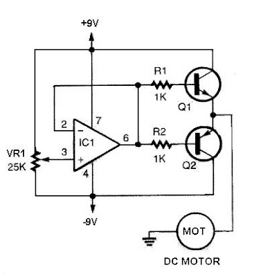
This DC motor controller circuit using a 741 operational amplifier operating as a voltage follower where its non inverting input is connected to the speed and rotation direction of a potentiometer VR1. When VR1 is at mid position, the op-amp output is near zero and both Q1 and Q2 is OFF.
When VR1 is turned towards the positive supply side, the output will go positive voltage and Q1 will supply the current to the motor and Q2 will be OFF. When VR1 is turned to the negative supply side, the op-amp output switches to the negative voltage and Q1 will turn OFF and Q2 ON which reverses the rotation of the motor's direction.
When VR1 is turned towards the positive supply side, the output will go positive voltage and Q1 will supply the current to the motor and Q2 will be OFF. When VR1 is turned to the negative supply side, the op-amp output switches to the negative voltage and Q1 will turn OFF and Q2 ON which reverses the rotation of the motor's direction.
 Skema Rangkaian DC Motor Controller Using 741 Op-Amp
 741 Op-Amp Pinout
As the potentiometer VR1 is moved toward either end, the speed increases in whichever direction it is turning. The TIP3055 Q1 NPN power transistor has a collector current specs of 15A and VCE0 of 60V DC. The MJE34 Q2 PNP power transistor has a collector current specs of 10A and VCE0 of 40V DC.
Posted by , Published at 7:28 AM and have


